Now that we can display quads, we'd like to be able to interact with one. Since we are creating a pixel simulation, we're going to draw pixels on our quad canvas.
We're going to need some kind of a structure to hold our color data (or matter data to be more specific), allow interaction the color data and then display that color data as an image. Because we'll be simulating the sand fall with compute shaders, it makes sense to draw with compute shaders too.
Setup
Our compute shader pipeline will allow CPU side to modify our color values and dispatch a command that will update those color values to an image.
We'll have to tell the GPU how many threads will be working. How much we'll need will be defined by our canvas size. Essentially, a thread will be looking at an individual pixel and determining what to do with it. The contents of our shader will be from that perspective. We decide how many times we need our shader to be called (exactly once per pixel).
First add some constants to main.rs as pre-work.
pub const CANVAS_SIZE_X: u32 = 512;
pub const CANVAS_SIZE_Y: u32 = 512;
pub const LOCAL_SIZE_X: u32 = 32;
pub const LOCAL_SIZE_Y: u32 = 32;
pub const NUM_WORK_GROUPS_X: u32 = CANVAS_SIZE_X / LOCAL_SIZE_X;
pub const NUM_WORK_GROUPS_Y: u32 = CANVAS_SIZE_Y / LOCAL_SIZE_Y;
Canvas sizes and local sizes will define the work group sizes for our compute shader. When we run the dispatch command to begin the computation, we'll be using these constants and defining how the GPU will split the work between threads.
The numbers we choose here matter quite a bit depending on the canvas size we choose. Sometimes you'll need to try various values, but for optimum performance the work group sizes should be multiples of 16. See also nvidia's article for more explanation on how one can aim to choose the sizes. And you can read here more about compute shaders.
But for now, as we'll just be drawing, you don't need to pay more attention to this. We'll talk more about this in the next part of the tutorial.
Let's create our simulation pipeline ca_simulator.rs to src. It'll just be a struct similar to our rendering pipelines, but instead will be working with a bit different shader API. We won't be needing vertices here.
use std::sync::Arc;

use bevy::math::{IVec2, Vec2};
use vulkano_util::renderer::DeviceImageView;
use vulkano::{
    buffer::{BufferUsage, CpuAccessibleBuffer},
    command_buffer::{
        AutoCommandBufferBuilder, CommandBufferUsage, PrimaryAutoCommandBuffer,
        PrimaryCommandBuffer,
    },
    descriptor_set::{PersistentDescriptorSet, WriteDescriptorSet},
    device::Queue,
    format::Format,
    image::{ImageUsage, StorageImage},
    pipeline::{ComputePipeline, Pipeline, PipelineBindPoint},
    sync::GpuFuture,
};

use crate::{
    utils::{create_compute_pipeline, storage_image_desc, storage_buffer_desc},
    CANVAS_SIZE_X, CANVAS_SIZE_Y, LOCAL_SIZE_X, LOCAL_SIZE_Y,
};

/// Creates a grid with empty matter values
fn empty_grid(
    compute_queue: &Arc<Queue>,
    width: u32,
    height: u32,
) -> Arc<CpuAccessibleBuffer<[u32]>> {
    CpuAccessibleBuffer::from_iter(
        compute_queue.device().clone(),
        BufferUsage::all(),
        false,
        vec![0; (width * height) as usize],
    )
    .unwrap()
}

/// Cellular automata simulation pipeline
pub struct CASimulator {
    compute_queue: Arc<Queue>,
    color_pipeline: Arc<ComputePipeline>,
    matter_in: Arc<CpuAccessibleBuffer<[u32]>>,
    matter_out: Arc<CpuAccessibleBuffer<[u32]>>,
    image: DeviceImageView,
}

impl CASimulator {
    /// Create new simulator pipeline for a compute queue. Ensure that canvas sizes are divisible by kernel sizes so no pixel
    /// remains unsimulated.
    pub fn new(compute_queue: Arc<Queue>) -> CASimulator {
        // In order to not miss any pixels, the following must be true
        assert_eq!(CANVAS_SIZE_X % LOCAL_SIZE_X, 0);
        assert_eq!(CANVAS_SIZE_Y % LOCAL_SIZE_Y, 0);
        let matter_in = empty_grid(&compute_queue, CANVAS_SIZE_X, CANVAS_SIZE_Y);
        let matter_out = empty_grid(&compute_queue, CANVAS_SIZE_X, CANVAS_SIZE_Y);

        let spec_const = color_cs::SpecializationConstants {
            canvas_size_x: CANVAS_SIZE_X as i32,
            canvas_size_y: CANVAS_SIZE_Y as i32,
            empty_matter: 0,
            constant_3: LOCAL_SIZE_X,
            constant_4: LOCAL_SIZE_Y,
        };

        // Create pipelines
        let color_pipeline = {
            let color_shader = color_cs::load(compute_queue.device().clone()).unwrap();
            // This must match the shader and inputs in dispatch
            let descriptor_layout = [
                (0, storage_buffer_desc()),
                (1, storage_buffer_desc()),
                (2, storage_image_desc()),
            ];
            create_compute_pipeline(
                compute_queue.clone(),
                color_shader.entry_point("main").unwrap(),
                descriptor_layout.to_vec(),
                &spec_const,
            )
        };
        // Create color image
        let image = StorageImage::general_purpose_image_view(
            compute_queue.clone(),
            [CANVAS_SIZE_X, CANVAS_SIZE_Y],
            Format::R8G8B8A8_UNORM,
            ImageUsage {
                sampled: true,
                transfer_dst: true,
                storage: true,
                ..ImageUsage::none()
            },
        )
        .unwrap();
        CASimulator {
            compute_queue,
            color_pipeline,
            matter_in,
            matter_out,
            image,
        }
    }

    /// Get canvas image for rendering
    pub fn color_image(&self) -> DeviceImageView {
        self.image.clone()
    }
}

mod color_cs {
    vulkano_shaders::shader! {
        ty: "compute",
        path: "compute_shaders/color.glsl"
    }
}
Because we are going to calculate things in parallel, we'll be needing two buffers. matter_in and matter_out. However, while only coloring, we'll be working as if we are using just one. We'll write to the input buffer on CPU side, then write the input buffer to the image as color. Well, to be precise, an image is another buffer too. We are creating CpuAccessibleBuffers just like we did for our canvas Mesh data.
You'll notice that we've added a new shader to be used too. Let's add that. compute_shaders/color.glsl.
#version 450

/*
Specialization constants. These get replaced by the values in CASimulator::new (anything with _id)
They are useful if you want to e.g. test different local sizes at runtime. However, if you did that, you'd have to recreate your pipeline. But we'll just pass these as constants from rust side.
*/
layout(constant_id = 0) const int canvas_size_x = 1;
layout(constant_id = 1) const int canvas_size_y = 1;
layout(constant_id = 2) const uint empty_matter = 1;
layout(local_size_x_id = 3, local_size_y_id = 4, local_size_z = 1) in;

/*
Buffers
*/
layout(set = 0, binding = 0) restrict buffer MatterInBuffer { uint matter_in[]; };
layout(set = 0, binding = 1) restrict writeonly buffer MatterOutBuffer { uint matter_out[]; };
layout(set = 0, binding = 2, rgba8) restrict uniform writeonly image2D canvas_img;

/*
Utility functions to be used in the various kernels:
*/

ivec2 get_current_sim_pos() {
    return ivec2(gl_GlobalInvocationID.xy);
}

int get_index(ivec2 pos) {
    return pos.y * canvas_size_x + pos.x;
}

uint read_matter(ivec2 pos) {
    return matter_in[get_index(pos)];
}

void write_matter(ivec2 pos, uint matter) {
    matter_out[get_index(pos)] = matter;
}

void write_image_color(ivec2 pos, vec4 color) {
    imageStore(canvas_img, pos, color);
}

// Transform a uint color to vec4 (r, g, b, a)
vec4 matter_color_to_vec4(uint color) {
    return  vec4(float((color >> uint(24)) & uint(255)) / 255.0,
                float((color >> uint(16)) & uint(255)) / 255.0,
                float((color >> uint(8)) & uint(255)) / 255.0,
                1.0);
}

// 0-1 linear  from  0-255 sRGB
vec3 linear_from_srgb(vec3 srgb) {
    bvec3 cutoff = lessThan(srgb, vec3(10.31475));
    vec3 lower = srgb / vec3(3294.6);
    vec3 higher = pow((srgb + vec3(14.025)) / vec3(269.025), vec3(2.4));
    return mix(higher, lower, cutoff);
}

vec4 linear_from_srgba(vec4 srgba) {
    return vec4(linear_from_srgb(srgba.rgb * 255.0), srgba.a);
}

void write_color_to_image(ivec2 pos) {
    uint matter = read_matter(pos);
    // Our swapchain is in SRGB color space (default by bevy_vulkano). The system tries to interpret our canvas image as such. But our canvas image is
    // UNORM (only way to ImageStore), thus we need to convert the colors to linear space. We are assuming that images
    // Are already in SRGB color space. When we render, the linear gets interpreted as SRGB.
    write_image_color(pos, linear_from_srgba(matter_color_to_vec4(matter)));
}

void main() {
    write_color_to_image(get_current_sim_pos());
}
We are using specialization_constants to pass values to our shaders as constants, which are created at runtime. These must match the ones described in CASimulator::new.
Because we are interested in colors, our buffers are filled with u32. 32 bits for rgba. That gets written to the image in above shader using glsl's imageStore function. gl_GlobalInvocationID.xy is used to get the exact pixel position on which the functions are run by the current thread.
Because we added another shader directory, let's make sure they get recompiled when changed.
// build.rs

//...
const COMPUTE_SHADER_DIR: &str = "compute_shaders";
fn main() {
    //...
    println!("cargo:rerun-if-changed={}", COMPUTE_SHADER_DIR);
}
Also, add following to utils.rs. We are using these in defining how the compute shader pipeline layout is created upon creation of our CASimulator.
use std::{collections::BTreeMap, iter::FromIterator, sync::Arc};

use vulkano::{
    descriptor_set::{
        layout::{
            DescriptorSetLayout, DescriptorSetLayoutBinding, DescriptorSetLayoutCreateInfo,
            DescriptorType,
        },
        PersistentDescriptorSet, WriteDescriptorSet,
    },
    device::{Device, Queue},
    image::ImageViewAbstract,
    pipeline::{
        layout::PipelineLayoutCreateInfo, ComputePipeline, GraphicsPipeline, Pipeline,
        PipelineLayout,
    },
    sampler::{Filter, Sampler, SamplerAddressMode, SamplerCreateInfo, SamplerMipmapMode},
    shader::{EntryPoint, ShaderStages, SpecializationConstants},
};

pub fn storage_buffer_desc() -> DescriptorSetLayoutBinding {
    DescriptorSetLayoutBinding {
        stages: ShaderStages::compute(),
        ..DescriptorSetLayoutBinding::descriptor_type(DescriptorType::StorageBuffer)
    }
}

/// Descriptor set layout binding information for image buffer
pub fn storage_image_desc() -> DescriptorSetLayoutBinding {
    DescriptorSetLayoutBinding {
        stages: ShaderStages::compute(),
        ..DescriptorSetLayoutBinding::descriptor_type(DescriptorType::StorageImage)
    }
}

/// Creates a compute pipeline from given shader, with given descriptor layout binding.
/// The intention here is that the descriptor layout should correspond the shader's layout.
/// Normally you would use `ComputePipeline::new`, which would generate layout for descriptor set
/// automatically. However, because I've split the shaders to various different shaders, each shader
/// that does not use a variable from my shared layout don't get the bindings for that specific variable.
/// See https://github.com/vulkano-rs/vulkano/pull/1778 and https://github.com/vulkano-rs/vulkano/issues/1556#issuecomment-821658405.
pub fn create_compute_pipeline<Css>(
    compute_queue: Arc<Queue>,
    shader_entry_point: EntryPoint,
    descriptor_layout: Vec<(u32, DescriptorSetLayoutBinding)>,
    specialization_constants: &Css,
) -> Arc<ComputePipeline>
where
    Css: SpecializationConstants,
{
    let push_constant_reqs = shader_entry_point
        .push_constant_requirements()
        .cloned()
        .into_iter()
        .collect();
    let set_layout = DescriptorSetLayout::new(
        compute_queue.device().clone(),
        DescriptorSetLayoutCreateInfo {
            bindings: BTreeMap::from_iter(descriptor_layout),
            ..Default::default()
        },
    )
    .unwrap();
    let pipeline_layout =
        PipelineLayout::new(compute_queue.device().clone(), PipelineLayoutCreateInfo {
            set_layouts: vec![set_layout],
            push_constant_ranges: push_constant_reqs,
            ..Default::default()
        })
        .unwrap();
    ComputePipeline::with_pipeline_layout(
        compute_queue.device().clone(),
        shader_entry_point,
        specialization_constants,
        pipeline_layout.clone(),
        None,
    )
    .unwrap()
}
Normally in Vulkano, you could automatically generate the pipeline layout information from the shaders using
ComputePipeline::new along with the shader macros, but I aim to split the calculation into multiple pipelines (for better code organization), which share the layout and currently the library omits layout variables that are not used in that specific shader generating invalid pipelines. Thus the pipeline is explicitly set in this project. This is something that you'll probably just want to copy paste. The idea is that there will be many shaders sharing the same layout.
Now, remove assets folder and TreeImage and let's create our pipeline and run the app.
// main.rs

fn setup(
    mut commands: Commands,
    vulkano_windows: NonSend<BevyVulkanoWindows>,
) {
    let simulator = CASimulator::new(primary_window_renderer.compute_queue());
    //...
    commands.insert_resource(simulator);
}

fn render(
    //...
    simulator: Res<CASimulator>,
) {
    //...
    let canvas_image = simulator.color_image();
    //...
    let after_images = fill_screen.draw(
        before,
        *camera,
        canvas_image,
        final_image.clone(),
        CLEAR_COLOR,
    );
    //...
}
If you run now, you should see nothing. But changing CLEAR_COLOR to [1.0;4], you'll see that our canvas is drawn. Just remember to zoom out.

Let's draw on it.
Draw Lines of Circles
If we were to just draw circles it would be hard to draw continuous lines between frames. Knowing this, let's do some prework before so we can draw lines and then we'll add the draw functionality to the simulator.
Add following to utils.rs.
use bevy::prelude::*;

/// Converts cursor position to world coordinates.
/// Convert mouse pos to be origo centered. Then scale it with camera scale, lastly offset
/// by camera position.
pub fn cursor_to_world(window: &Window, camera_pos: Vec2, camera_scale: f32) -> Vec2 {
    (window.cursor_position().unwrap() - Vec2::new(window.width() / 2.0, window.height() / 2.0))
        * camera_scale
        - camera_pos
}

/// Mouse world position
#[derive(Debug, Copy, Clone)]
pub struct MousePos {
    pub world: Vec2,
}

impl MousePos {
    pub fn new(pos: Vec2) -> MousePos {
        MousePos {
            world: pos,
        }
    }

    /// Converts world position to canvas position:
    /// Inverts y and adds half canvas to the position (pixel units)
    pub fn canvas_pos(&self) -> Vec2 {
        self.world + Vec2::new(CANVAS_SIZE_X as f32 / 2.0, CANVAS_SIZE_Y as f32 / 2.0)
    }
}

/// Gets a line of canvas coordinates between previous and current mouse position
pub fn get_canvas_line(prev: Option<MousePos>, current: MousePos) -> Vec<IVec2> {
    let canvas_pos = current.canvas_pos();
    let prev = if let Some(prev) = prev {
        prev.canvas_pos()
    } else {
        canvas_pos
    };
    line_drawing::Bresenham::new(
        (prev.x.round() as i32, prev.y.round() as i32),
        (canvas_pos.x.round() as i32, canvas_pos.y.round() as i32),
    )
    .into_iter()
    .map(|pos| IVec2::new(pos.0, pos.1))
    .collect::<Vec<IVec2>>()
}
cursor_to_world will convert our mouse position to world coordinates. MousePos::canvas_pos will do the same, but convert the world coordinate to canvas. Then we can directly use those coordinates to access the indices in our grid buffer.
Don't forget to add the line_drawing dependency to Cargo.toml.
line_drawing = "1.0.0"Let's also add an update_mouse system to main.rs
use crate::utils::{cursor_to_world, get_canvas_line, MousePos};

///...main
        .add_system(update_mouse)
///

/// Mouse position from last frame
#[derive(Debug, Copy, Clone)]
pub struct PreviousMousePos(pub Option<MousePos>);

/// Mouse position now
#[derive(Debug, Copy, Clone)]
pub struct CurrentMousePos(pub Option<MousePos>);

/// Setup...
    commands.insert_resource(PreviousMousePos(None));
    commands.insert_resource(CurrentMousePos(None));
///...

/// Update mouse position
fn update_mouse(
    windows: Res<Windows>,
    mut _prev: ResMut<PreviousMousePos>,
    mut _current: ResMut<CurrentMousePos>,
    camera: Res<OrthographicCamera>,
) {
    _prev.0 = _current.0;
    let primary = windows.get_primary().unwrap();
    if primary.cursor_position().is_some() {
        _current.0 = Some(MousePos {
            world: cursor_to_world(primary, camera.pos, camera.scale),
        });
    }
}
Now that we have our mouse positions queryable: A separate system updating our mouse canvas coordinate values making it easy for our other system to interact with the grid to our simulator. Add following to the simulator.
// ca_simulator.rs
    /// Are we within simulation bounds?
    fn is_inside(&self, pos: IVec2) -> bool {
        pos.x >= 0 && pos.x < CANVAS_SIZE_X as i32 && pos.y >= 0 && pos.y < CANVAS_SIZE_Y as i32
    }

    /// Index to access our one dimensional grid with two dimensional position
    fn index(&self, pos: IVec2) -> usize {
        (pos.y * CANVAS_SIZE_Y as i32 + pos.x) as usize
    }

    /// Draw matter line with given radius
    pub fn draw_matter(&mut self, line: &[IVec2], radius: f32, matter: u32) {
        let mut matter_in = self.matter_in.write().unwrap();
        for &pos in line.iter() {
            if !self.is_inside(pos) {
                continue;
            }
            let y_start = pos.y - radius as i32;
            let y_end = pos.y + radius as i32;
            let x_start = pos.x - radius as i32;
            let x_end = pos.x + radius as i32;
            for y in y_start..=y_end {
                for x in x_start..=x_end {
                    let world_pos = Vec2::new(x as f32, y as f32);
                    if world_pos
                        .distance(Vec2::new(pos.x as f32, pos.y as f32))
                        .round()
                        <= radius
                    {
                        if self.is_inside([x, y].into()) {
                            // Draw
                            matter_in[self.index([x, y].into())] = matter;
                        }
                    }
                }
            }
        }
    }
And add a draw system to main.rs.
        .add_system(draw_matter)
//...

fn draw_matter(
    mut simulator: ResMut<CASimulator>,
    prev: Res<PreviousMousePos>,
    current: Res<CurrentMousePos>,
    mouse_button_input: Res<Input<MouseButton>>,
) {
    if let Some(current) = current.0 {
        if mouse_button_input.pressed(MouseButton::Left) {
            let line = get_canvas_line(prev.0, current);
            // Draw red
            simulator.draw_matter(&line, 4.0, 0xff0000ff);
        }
    }
}
We can draw now, but our drawing is not visible yet. Let's finish our compute functionality to display our drawings. Add following to CASimulator.
// ca_simulator.rs

    /// Step simulation
    pub fn step(&mut self) {
        let mut command_buffer_builder = AutoCommandBufferBuilder::primary(
            self.compute_queue.device().clone(),
            self.compute_queue.family(),
            CommandBufferUsage::OneTimeSubmit,
        )
        .unwrap();

        // Finally color the image
        self.dispatch(&mut command_buffer_builder, self.color_pipeline.clone());

        // Finish
        let command_buffer = command_buffer_builder.build().unwrap();
        let finished = command_buffer.execute(self.compute_queue.clone()).unwrap();
        let _fut = finished.then_signal_fence_and_flush().unwrap();
    }

    /// Append a pipeline dispatch to our command buffer
    fn dispatch(
        &mut self,
        builder: &mut AutoCommandBufferBuilder<PrimaryAutoCommandBuffer>,
        pipeline: Arc<ComputePipeline>,
    ) {
        let pipeline_layout = pipeline.layout();
        let desc_layout = pipeline_layout.set_layouts().get(0).unwrap();
        let set = PersistentDescriptorSet::new(desc_layout.clone(), [
            WriteDescriptorSet::buffer(0, self.matter_in.clone()),
            WriteDescriptorSet::buffer(1, self.matter_out.clone()),
            WriteDescriptorSet::image_view(2, self.image.clone()),
        ])
        .unwrap();
        builder
            .bind_pipeline_compute(pipeline.clone())
            .bind_descriptor_sets(PipelineBindPoint::Compute, pipeline_layout.clone(), 0, set)
            .dispatch([NUM_WORK_GROUPS_X, NUM_WORK_GROUPS_Y, 1])
            .unwrap();
    }
Now there's a bit more going on here. step creates a command buffer which gets filled with our dispatch commands. In this case only color_pipeline at this point.Then We execute the command(s) in our compute queue.
then_signal_fence_and_flush gives us a future which we could wait on representing the point where the GPU is done with the work.
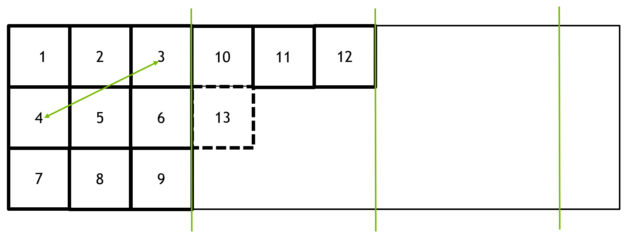
Note the variables we pass to dispatch command. We tell the drivers to run our compute shaders for X and Y work group counts. In our case e.g. 512 / 32 = 16. So there will be 16 x 16 groups that each run the
shaders at 32 x 32 local sizes. So our work group size is 1024. It will be pretty much like below (nvidia's picture). Thus the shader gets called per pixel.
Finally, let's add a simulate system to main.rs to run our simulation.
        .add_system(simulate)

/// Step simulation
fn simulate(mut sim_pipeline: ResMut<CASimulator>) {
    sim_pipeline.step();
}
Now you should see red drawings. However, the Y is flipped. Let's fix that next.
Drawing a quad is essentially the same as sprite drawing, and in games you might want to flip X or Y axis of your sprites. In our case now we could do exactly that or we could edit our mouse position calculations or grid buffer access etc.
Our image is drawn correctly just like we determined in the previous part of the tutorial, but the way we access our grid data is inverted. Or we could say our grid data is inverted. Let's leave that as is and instead edit our draw pipeline to allow a y flip. That way we can keep our coordinate system intact and draw with coordinates that grow upwards in Y axis. There's not just one way to do this, but many.
// Add to FillScreenRenderPass::draw inputs
        flip_x: bool,
        flip_y: bool,

// Pass to draw command
        let cb =
            self.quad_pipeline
                .draw(target_image.width_height(), camera, image, flip_x, flip_y);

// Add to DrawQuadPipeline::draw inputs
        flip_x: bool,
        flip_y: bool,

        //...
        let push_constants = vs::ty::PushConstants {
            world_to_screen: camera.world_to_screen().to_cols_array_2d(),
            // Scale transforms our 1.0 sized quad to actual pixel size in screen space
            scale: [
                dims.width() as f32 * if flip_x { -1.0 } else { 1.0 },
                dims.height() as f32 * if flip_y { -1.0 } else { 1.0 },
            ],
        };
We will flip the vertex scale in our push constants if true. And flip y in main.rs render system.
    let after_images = fill_screen.draw(
        before,
        *camera,
        canvas_image,
        final_image.clone(),
        CLEAR_COLOR,
        false,
        true,
    );
Now it's correct. Let's finish this part of the tutorial by adding some dynamic settings to edit brush size
Add following to main.rs
pub struct DynamicSettings {
    pub brush_radius: f32,
    pub draw_matter: u32,
}

impl Default for DynamicSettings {
    fn default() -> Self {
        Self {
            brush_radius: 4.0,
            draw_matter: 0xff0000ff,
        }
    }
}

// In setup
    commands.insert_resource(DynamicSettings::default());

// In draw matter
fn draw_matter(
    //...,
    settings: Res<DynamicSettings>, //New
) {
            //...
            simulator.draw_matter(&line, settings.brush_radius, settings.draw_matter); // Edited
            //...
}
And to gui.rs
pub fn user_interface(
//...,
mut settings: ResMut<DynamicSettings>, //New
) {
//...
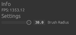
ui.heading("Info"); // New
if let Some(diag) = diagnostics.get(FrameTimeDiagnosticsPlugin::FPS) {
//...
}
ui.heading("Settings"); // New
ui.add(egui::Slider::new(&mut settings.brush_radius, 0.5..=30.0).text("Brush Radius")); // New
//...
}Now you should be able to draw various sized red circle lines.
The next part of the tutorial is the fun part! We'll be implementing the sand fall shader pipelines and do some actual simulation. We'll also improve our matter from u32 color to be a more useful struct holding matter identifiers in addition to the color.
You can checkout the full source code for this part of the tutorial here
Give feedback here
Was this page helpful?